Endless Possibilities with Flight Vehicle Dynamic Modeling
This section describes in detail the operation of the flight vehicle modeling program and the flexible spacecraft modeling program that generate vehicle state-space systems for simulations and control analysis. It also describes the actuator modeling program which implements several types of actuator dynamic models for engine thrust vectoring (TVC) and aerosurfaces control and it creates actuator state-space models that can be coupled with the vehicle dynamics.
Flight Vehicle and Spacecraft Modeling Program
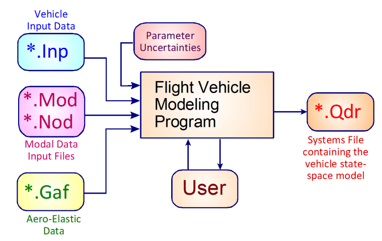
The Flixan flight vehicle modeling program is used for generating dynamic systems of flight vehicles at fixed flight conditions. The models can be rigid or flexible structures, and they may include propellant sloshing, tail-wags-dog dynamics, and other features defined by options. The vehicle dataset is read by the program from an input file (.Inp) which may include more datasets corresponding to other Flixan routines, such as systems combination, actuators, etc. The vehicle dataset contains the parameters needed to create the vehicle models. They include: mass properties, aerodynamic data, trajectory data, engine and aerosurface data, propellant sloshing parameters, sensor data and flexibility. Structural flexibility, aero-elasticity, and dynamic coupling between the structure and the aerosurfaces can be included by processing additional modal data that include: flex modes, aero-elastic coefficients and inertial coupling coefficients which are processed together with the vehicle data. For robustness mu-analysis, mu-synthesis and for developing parameter uncertainty models, the program requires additional parameter variations datasets which must be included in the input file and processed with the vehicle data. The program runs either interactively or in batch mode. The user must first select the folder where the vehicle project files are located from the directory selector. The Flixan main menu comes up, and the program is selected by clicking on “Program Functions”, then “Flight Vehicle/ Spacecraft Modeling Tools”, and then “Flight Vehicle State-Space Models”. The vehicle state-space model is saved in a systems file (.Qdr) for further analysis.
The operation of the vehicle modeling program is described in the first video. The second video describes how to use the Flixan Mode Selection utility to select and prepare a set of modes that can be combined and processed together with the vehicle data and generate the flexible vehicle model. Aero-elasticity requires additional coefficients that couple the aerodynamics with the flex modes. The program requires a structural model that is created from a Nastran type of finite elements program consisting of mode frequencies and shapes, and it is formatted to be read by Flixan. This video describes how we use this program to select and prepare a reduced set of modes which are saved in the vehicle input data file. They are processed with the vehicle data by the vehicle modeling program to produce the flex vehicle state-space system.
The Flixan flight vehicle modeling program is used for creating dynamic systems of flight vehicles at fixed flight conditions. The models can be rigid or flexible structures that include propellant sloshing, tail-wags-dog dynamics, and may include several other options. The vehicle input data are read by the program from datasets that include: mass properties, aerodynamic data, trajectory, engine and aero-surface data, propellant sloshing parameters, sensor data, and flexibility. The dynamic systems created are saved in a systems file for further analysis. Structural flexibility, aero-elasticity, and dynamic coupling between the structure and the aerosurfaces can be included by processing additional modal data that include: flex modes, aero-elastic coefficients, and inertial coupling coefficients. For robustness mu-analysis and mu-synthesis and for developing parameter uncertainty models, the program requires parameter variations datasets which are included in the input file. The program runs either interactively or in batch mode.
This video describes how to use the Flixan Mode Selection utility to select and prepare a set of modes that can be combined and processed together with the vehicle data and to create a flex vehicle model. Aero-elasticity requires additional coefficients that couple the aerodynamics with the flex modes. The program requires a structural model that is created from a Nastran type of finite elements program consisting of mode frequencies and shapes, and it is formatted to be read by Flixan. This video describes how we use this program to select and prepare a reduced set of modes which are saved in the vehicle input data file. They are processed with the vehicle data by the vehicle modeling program to produce the flex vehicle state-space system.
Flexible Space Structures Modeling Program
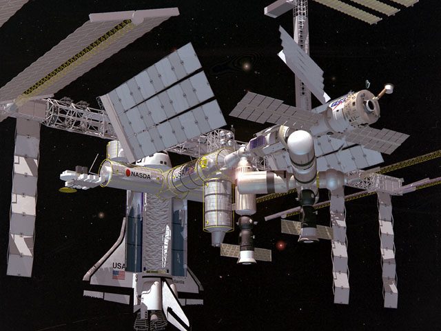
The Flexible Spacecraft or Space Structures modeling program is different from the vehicle modeling program. It creates dynamic systems of flexible space structures from Finite Element Models. It does not include its own dynamic equations but it simply manages an already created finite element model of a flexible spacecraft and it generates state-space systems between specific inputs and output types, which are used for control analysis. The entire dynamic model of the spacecraft is already defined in the structural data. It is used to create models for flexible space structures, such as, satellites, space stations with rotating solar arrays and optical sensors, etc. It is not a multi-body, non-linear simulation, but can be used for small angle relative appendage rotations. The user must define a set of inputs and outputs, select a number of structural modes using a mode-selection process, and the program creates the state-space systems. The locations and directions of the actuators and sensors are defined in the input file dataset. The input dataset is created by the user interactively. It also includes a set of modes which are selected from the modal data file via an interactive mode-selection process. The spacecraft system is saved in the systems file (.Qdr).
The inputs are either, external forces and torques, such as: reaction control thrusters, control moment gyros, and disturbances, control torques at the hinges of pivoting bodies, such as solar arrays and gimbaling telescopes. The system outputs are either translational or rotational sensors that measure position, velocity, or acceleration at selected locations on the spacecraft, or gimbaling sensors measuring rotation angles of pivoting appendages relative to the spacecraft. The user interactively defines the locations, types and directions of the actuators and sensors which are the spacecraft inputs and outputs. The input torques are either external or internal applied at solar array joints or gimbaling payloads. The linear models are used for analyzing spacecraft attitude control stability, its responses to commands and to external disturbances, analyzing the dynamic interactions between spacecraft structure and gimbal control loops, performing small angle simulations, designing payload pointing servo-systems, and analyzing the jitter effects of spacecraft disturbances to optical instruments or to micro-gravity sensors as a result of the dynamic interaction between the structure and the control systems. The flex models (without the rigid-body modes) can also be combined in parallel with non-linear rigid-body spacecraft models in 6DoF simulations. This is an easy method to include flexibility in non-linear 6DoF simulations because the forces and torques are applied to both models and their outputs are combined.
This video describes the Flexible Spacecraft or Space Structures modeling program, which is different from the vehicle modeling program. This program is mainly used for processing already created finite element models for flexible spacecraft applications. It is used for reducing them, reformatting and converting them into state-space systems for analysis and simulations. The user interactively defines the locations, types and directions of the actuators and sensors which are the model inputs and outputs. The input torques are either external or internal applied at joints, such as gimbals. The models are used for analyzing control stability, the dynamic interactions between spacecraft structure and gimbal control loops, performing small angle simulations, and analyzing the jitter effects of spacecraft disturbances on optical instruments or micro-gravity sensors. The flex models (without rigid-body modes) may also be combined in parallel with non-linear rigid-body spacecraft models in 6DoF simulations. This is an easy method to include flexibility in detail 6DoF simulations because the forces and torques are applied to both models and the outputs are combined.
Actuator Modeling Program
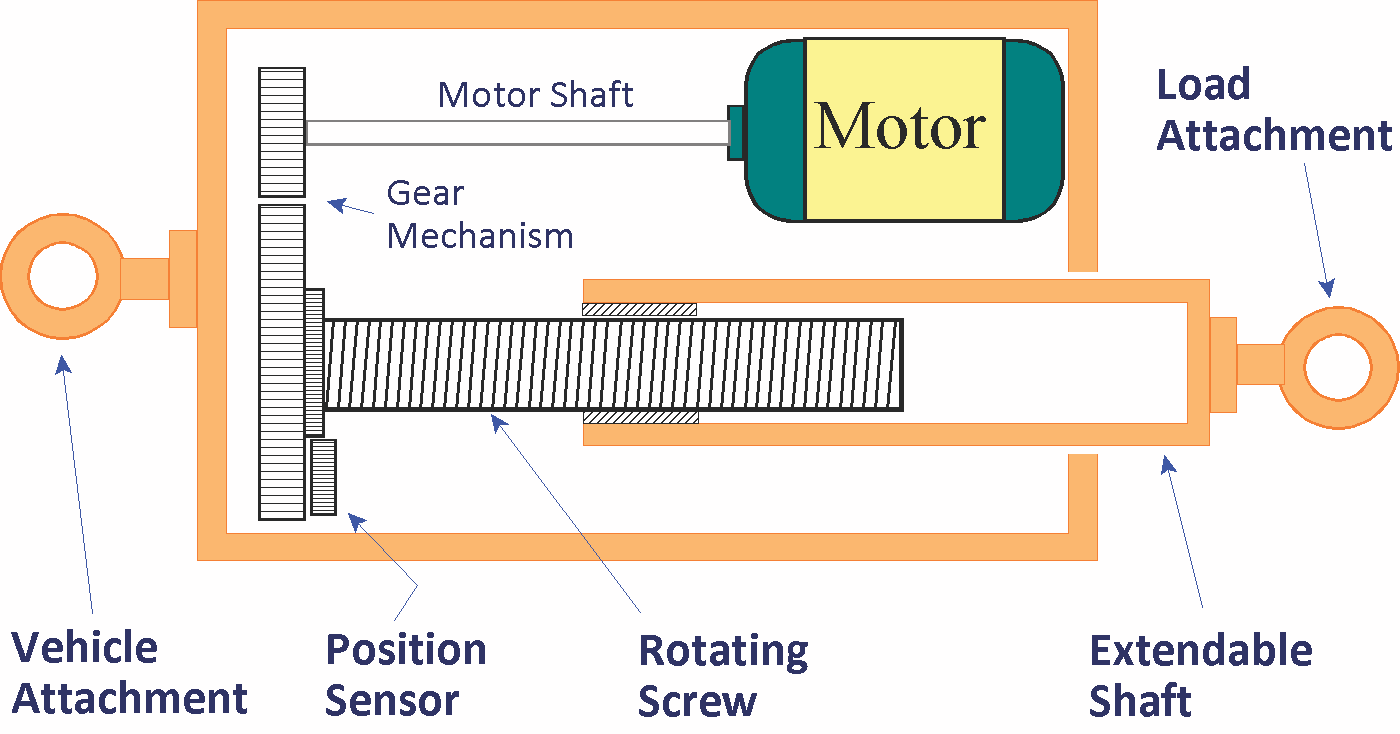
Flight vehicles are controlled by TVC engines or aero-surfaces that rotate about a gimbal or hinge. The servo-actuator provides the control force necessary to rotate the effector in the direction to maneuver the vehicle and to stabilize it. Since the actuator dynamics greatly couple with the vehicle and affect its motion, we will dedicate this section to describe some commonly used actuator models with examples. The actuator consists of a hydraulic or electro-mechanical system and a position control servo that controls the position of an extendable shaft which rotates the effector. One side of the actuator is attached to the vehicle and the other side which extends is attached to the pivoting effector. Each actuator device receives a deflection command signal from flight control via the mixing logic matrix. The actuator system has a sensor that measures the extension of the shaft and provides feedback to the position control servo which adjusts its position according to the command received. In launch vehicles, a small rotation of the thrust vector angle about the gimbal (typically between ±5° and ±10° in pitch and in yaw) is sufficient to create normal and lateral control forces to control the vehicle and to overcome the wind disturbances torques. In aircraft the control-surface deflections are larger, ±40° relative to the trim position and they rotate about a hinge line which is parallel to the aerosurface and the actuator provides the force to rotate it against the aerodynamic loads. The rotation of the control surface changes the airflow around the aircraft and creates the aerodynamic forces and moments needed to trim and to control the vehicle.
The Flixan actuator modeling program includes models of 5 different actuator types, from simple generic, hydraulic models, and two electro-mechanical models. The dynamic models include the rotation of the effector load relative to the hinge and the shaft position control system. The actuator parameters are read by the program from an input file dataset. They include load inertia, stiffnesses, damping, gear ratios, gains, etc. They are processed to create the state state-space model which is placed in the systems file. The input signals to each actuator system are the gimbal position command in (rad), and the load-torque input in (ft-lb) at the hinge which is a mechanical feedback loop coming from the vehicle hinge moment outputs. The actuator model outputs are: effector deflection in radians, rate, and gimbal acceleration which produces the tail-wags-dog effect.
The Actuators provide the control forces that rotate the engine nozzles about the gimbal or the aerosurfaces of an aircraft about the hinges. An actuator is either hydraulic or electro-mechanical and it has an extendable shaft. One side of the actuator is attached to the vehicle and the other side which extends is attached to the rotating effector, which is either a nozzle or an aerosurface. The Flixan program provides the capability to model several types of actuators, from simple generic, hydraulic, to electro-mechanical models. Five different model types are included in the actuator modeling program and the user must provide the parameters in a dataset which are processed to create a linear state model. Each actuator device receives a deflection command signal from flight control via the mixing logic matrix. The actuator outputs are: effector deflection in radians, rate, and acceleration, that connect to the vehicle model inputs. The accelerations are used for implementing the tail-wags-dog effects. Each aerosurface actuator also includes a load-torque input which is a mechanical feedback loop coming from the vehicle hinge moment outputs.
