Spacecraft Modeling and Control Design
In this section we demonstrate the capabilities of the Flixan vehicle modeling and flex spacecraft modeling programs to create spacecraft dynamic models that include structural flexibility. The state-space models are controlled by reaction jets (RCS), reaction wheels (RW) and control moment gyros (CMG) and they include momentum coupling and gravity-gradient dynamics. The Flixan control design tools are also used to design the control laws. The analysis is completed with classical stability, sensitivity to disturbances, and robustness mu-analysis using both Flixan and Matlab programs.
Flex Space Station Attitude Control and Momentum Management
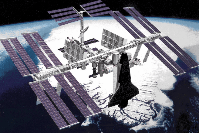
In this example we will design and analyze the control system of a large and flexible Space Station which is in orbit around the earth. The Space Station configuration consists of a truss structure with some attached modules for the crew, equipment, experiments, etc. which are located near the center of the structure. The vehicle has a circular orbit and its attitude is mostly constant relative to the Local Vertical Local Horizontal (LVLH) frame. The LVLH x-axis is in the direction of the velocity vector, the z-axis is pointing towards the earth center and the y-axis towards the right solar array.
The attitude control system (ACS) stabilizes the spacecraft attitude by using reaction control jets (RCS) and control moment gyros (CMG). We will design RCS and CMG control laws, momentum desaturation, and a control mode that stabilizes the Station attitude and in addition it manages the CMG momentum which is limited in magnitude by commanding the spacecraft to an attitude where the aerodynamic and gravity gradient torques balance out. We will create several spacecraft models for different analysis and introduce structural modes. Then, we will analyze the control system’s stability and performance using simulations and classical frequency response analysis methods.
Fast Maneuvering Flexible Spacecraft with RCS and CMGs
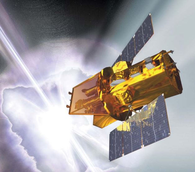
In this example we have a spacecraft that requires high precision pointing for optical instruments, such as a telescope, or laser beam. The spacecraft Line-of-Sight (LOS) is along the body x-axis and it is pointing at targets. It is pointed at one target for a period of time and then it rotates to point at different target, and then another. The spacecraft is described as agile because under normal operations it is constantly maneuvering between targets and the retargeting must be completed as fast as possible. The on-board Attitude Control System (ACS) is operating in different control modes depending on the circumstances. It uses a combination of RCS jets and Single-Gimbal Control Moment Gyros (SG-CMG). In normal mode of operation the ACS uses four Control Moment Gyros which provide high torque required for fast maneuvering between targets. The spacecraft uses the RCS jets for momentum desaturation and also as an ACS backup. It also has a fixed thruster engine for orbital maneuvering. The spacecraft structure is flexible because of the solar arrays and other communication appendages that require finite element modeling and detailed flex analysis. To further complicate the analysis, there is also a propellant tank containing fuel for the main engine and the RCS jets. The propellant sloshing inside the tank during orbital maneuvering affects the vehicle stability and introduces oscillatory disturbances that require analysis because they may degrade the LOS pointing accuracy.
Space Telescope Attitude Control with RCS and Reaction Wheels
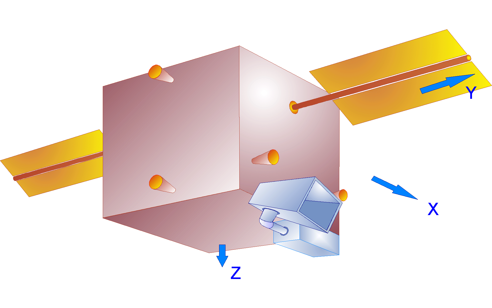
In this example we have a satellite with a pair of solar arrays and an optical instrument that can rotate in two directions (azimuth and elevation) relative to the spacecraft. The spacecraft attitude is controlled by 3 wheels. Two of the wheels are reaction wheels with their spin axes tilted 20° from the spacecraft y axis and they can provide control torques only in pitch and yaw axes. The third wheel is a momentum wheel and it spins at constant rate. It is not used for attitude control but it produces a constant pitch momentum bias of -40 (ft-lb-sec). The momentum bias provides a stiffening effect in the out-of-plane directions and passive roll/ yaw stabilization. The lateral RW control law takes advantage of the roll/yaw dynamic coupling and it dampens the nutation resonance. By stabilizing the roll axis, it also stabilizes yaw due to the gyroscopic coupling between the two axes. The spacecraft also includes 7 RCS jets for attitude control and momentum desaturation.
Interceptor Spacecraft
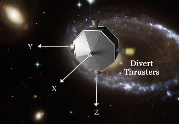
In this example we will analyze a guided intercept between two space vehicles: an interceptor which is a kinetic vehicle (KV) and a target that may be a meteorite heading towards the earth, space debris, or an enemy missile. A typical space intercept is divided into three phases: The boost phase where the KV is attached to an accelerating booster that is moving towards the target and acquires sufficient kinetic energy to destroy the target by impact, the Mid-Course guidance phase that attempts to align the direction of the KV in a collision course with the target by predicting the target’s future trajectory, and the final phase, the End-Game guidance which begins when the interceptor is sufficiently close to acquire the target position in its field of view and ends when the KV impacts and destroys the target. In this example will design, analyze and simulate the end-game guidance.