Features of the Flixan® Program
This section describes the general purpose of the Flixan program. It presents the equations of motion of atmospheric flight vehicles and spacecraft. It includes methodologies of combining multiple effectors and different types of vehicle actuators, such as TVC or throttling engines, RCS, and aerosurfaces. It includes methods of trimming the vehicle effectors along a trajectory and analyzing the static performance and controllability of generic and conceptual flight vehicles. It also includes different types of actuator models for aerosurfaces and TVC, detail descriptions of the flight vehicle and spacecraft modeling programs and includes the most commonly used control design tools.
Introduction to the Flixan Program
The Flixan program creates state-space systems of different types of flight vehicles at fixed flight conditions. Vehicles such as aircraft, launch vehicles, reentry vehicles, spacecraft, or any in-between vehicle concept that is controlled by gimbaling or throttling TVC engines, aerosurfaces, RCS, CMGs and Reaction Wheels. It was motivated by the need to create dynamic models of different types of conceptual flight vehicles, fast and at different levels of complexity. They can be airplanes, gliders, launch and re-entry vehicles, rocket-planes, missiles, satellites, space-stations, or any type of generic vehicle consisting of blended features from the above. The modeling details may vary from simple rigid-body models to very complex vehicles that include high order dynamics, such as: actuator types, effector combination logic, tail-wags-dog, hinge-moments, wind-gusts, fuel sloshing, flexibility and aero-elasticity, and including hundreds of structural modes. The complexity of the model is defined in the input data and in the options selected. The designer begins with a simple rigid model and gradually includes more details increasing the model complexity as additional parameters become available, such as: actuator, engine and aerosurface parameters, flexibility data, propellant sloshing, etc.
The flight vehicle dynamic models are either atmospheric or spacecraft. They are used by stability and control engineers to develop control laws, analyze stability, robustness and develop simulations that would allow a human pilot or an autopilot to maneuver the vehicle and to perform its mission. The vehicle configuration is defined in the input data which consists of: mass properties, aerodynamic data, trajectory data, engine data, slosh parameters, aerosurfaces, hinge moment coefficients, aero-elastic coefficients, control moment gyros, reaction wheels, different types of sensors, etc. This introduction describing the program features and functions, the input and output files and how it interacts with the user. It describes how to select the flexible modes from Nastran files and include them in the vehicle model, the system conversion and system combination utilities, how to run the Flixan program interactively or in batch mode and how to export systems and data to Matlab for further analysis.
This video is an introduction to the Flixan program. It describes the program features and functions, the input and output files and how the program interacts with the user. It describes how to select flex modes from Nastran outputs and include modal data in the vehicle models. It also describes several other utilities for converting and combining state-space systems, how to run the program interactively or in batch mode and how to export systems and data to Matlab format for further analysis.
Flight Vehicle Equations
This section describes the equations of motion of generic atmospheric vehicles such as aircraft, launch vehicles, missiles and reentry vehicles which are controlled by aerosurfaces, gimbaling engines, throttling engines, and reaction control jets. The equations of motion describe how the vehicle will move in response to applied forces. For example, simple equations describe how a rocket will accelerate when a constant thrust is provided by the rocket’s engine.
More difficult equations describe how the sloshing of the propellant in a rocket’s fuel tank will cause the rocket’s structure to vibrate or throw the rocket off-course. Flexibility equations describe how the structure of an aircraft or a rocket is excited by aerodynamic forces, external forces and torques or by the engines pivoting and thrust variations. Another type of modeling would be to predict, in a mathematical equation, how an aircraft will respond to hitting an updraft in the atmosphere, or how it will respond to the deflection of various control surfaces at different airspeeds. These are differential equations, in which the rate of change of some quantity is described as being dependent upon other quantities and their rates of change. The equations include propellant sloshing, tail-wags-dog dynamics, structural flexibility, aero-elasticity effects, and dynamic coupling between the vehicle and the actuators. They are implemented in the Flixan flight vehicle modeling program that converts vehicle data into state-space systems to be used for control analysis and simulations.
This tutorial describes the equations of motion of a generic flight vehicle that is controlled by aerosurfaces, gimbaling and throttling engines, and RCS jets. It includes propellant sloshing, tail-wags-dog effects, structural flexibility, aero-elasticity effects, and dynamic coupling with the vehicle actuators. The equations are implemented in the Flixan flight vehicle modeling program that converts the vehicle data into state-space systems for control analysis and simulations.
Spacecraft Equations
This section describes the equations of motion for a rigid body spacecraft that is controlled by reaction control jets (RCS), and also an array of momentum exchange devices, such as, reaction wheels (RWA), single-gimbal control moment gyros (SG-CMG), and double-gimbal control moment gyros (DG-CMG). This section describes the equations of motion of a rigid spacecraft that is controlled by reaction control jets (RCS), and by an array of momentum exchange devices, such as, reaction wheels and control moment gyros. The equations include the dynamic interaction between the spacecraft and the momentum exchange devices which control the spacecraft attitude by exchanging angular momentum with the spacecraft. Reaction wheels consist of a spinning rotor whose spin axis is fixed relative to the spacecraft and its spin rate is maintained close to zero. Its speed is increased or decreased to generate a reaction torque about the spin axis. CMGs are spinning at a constant high rate and they produce torques by rotating the spin axis. A cluster of CMGs is adjusted to produce zero average momentum on the spacecraft. When the momentum approaches saturation levels it is dumped by firing the RCS jets or by other means. The spacecraft equations may also include rotating appendages, such as, solar arrays or pointing optical devices that interact with the spacecraft. Structural flexibility is included as a separate flex subsystem dynamically coupled with the rigid-body model. The equations are implemented in the Flixan flight vehicle modeling program that converts the vehicle data into state-space systems.
This video presents the equations of motion of spacecraft which are controlled by reaction control jets, reaction wheels, and control moment gyros. It includes the dynamic effects between the spacecraft and the momentum exchange devices. The spacecraft equations include structural flexibility and rotating appendages, such as, solar arrays or pointing devices that interact with the spacecraft. The equations are implemented in the Flixan flight vehicle modeling program that converts the vehicle data into state-space systems for control analysis and simulations.
Mixing Logic for Combining Effectors
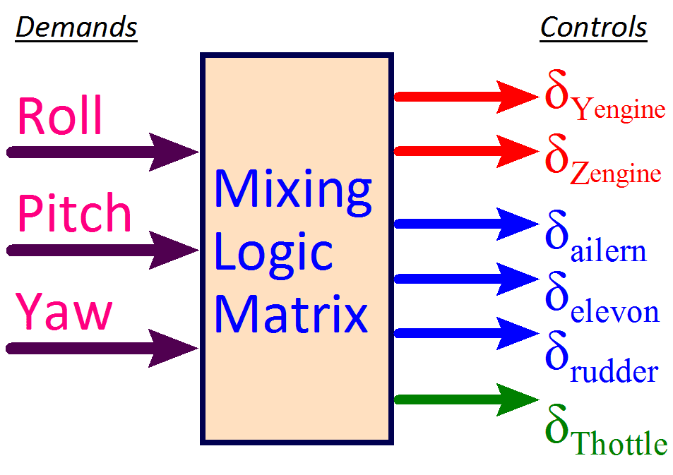
The effector combination or mixing logic is a matrix (Kmix) that connects between the flight control system outputs and the actuator inputs. Its purpose is to convert the FCS acceleration demands to TVC or aerosurface deflections or to thrust variations commands. This section describes the equations of motion of generic atmospheric vehicles such as aircraft, launch vehicles, missiles and reentry vehicles which are controlled by aerosurfaces, gimbaling engines, throttling engines, and reaction control jets. The equations of motion describe how the vehicle will move in response to applied forces. For example, simple equations describe how a rocket will accelerate when a constant thrust is provided by the rocket’s engine. More difficult equations describe how the sloshing of fuel in a rocket’s fuel tank will cause the rocket’s structure to vibrate or throw the rocket off-course. Flexibility equations describe how the structure of an aircraft is excited by aerodynamic forces, external forces and torques or by pivoting engines and thrust variations. Another type of modeling would be to predict, in a mathematical equation, how an aircraft will respond to hitting an updraft in the atmosphere, or how it will respond to the deflection of various control surfaces at different airspeeds. These are differential equations, in which the rate of change of some quantity is described as being dependent upon other quantities and their rates of change. The equations include propellant sloshing, tail-wags-dog dynamics, structural flexibility, aero-elasticity effects, and dynamic coupling with the vehicle actuators. They are implemented in the Flixan flight vehicle modeling program that converts vehicle data into state-space systems for control analysis and simulations.
This video describes the effector combination algorithm which produces a matrix that connects between the flight control system outputs and the actuator inputs. It converts the flight control acceleration demands to engine or aerosurface deflections or to thrust variation commands. The inputs to the algorithm are vehicle and effector data, and the control directions, usually 3 rotations plus some translations. The output is a matrix that converts the control inputs to effector deflections.
Static Performance Analysis and Trimming of Effectors
Designs of conceptual flight vehicles must meet, among other things, controllability, stability, and maneuverability performance requirements in order to be certified for operation. However, a flight vehicle’s ability to meet these requirements is often limited by performance, stability, or control authority availability. Thus, it is essential for designers to evaluate the overall performance and control authority of candidate concepts in a static sense, early in the design process, and prior to dynamic analysis. Designers normally consider numerous possible vehicle configurations before stability and control system groups begin their analysis and design. There is a need, therefore, for a quick and methodical tool for analyzing new flight vehicle concepts, controlled by multiple types of effectors and to provide a systematic design process by analyzing a number of critical static performance parameters which are calculated from basic vehicle data. The methodology presented in this document is implemented in the Flixan static analysis program. It is intended to bridge the gap between concept and realism and to simplify the task of the flight control systems engineer in evaluating new concepts, satisfying missions and meeting performance expectations, by analyzing a number of critical static performance parameters such as static stability, controllability and maneuverability when the vehicle is flying along a known trajectory.
The design of a new flight vehicle from the flight control point of view undergoes through various phases of design and analysis. The designer begins by collecting the vehicle data, which initially is limited to basics and some of the numbers may have to be roughly estimated or guessed. As the design progresses, however, and new numbers become available the database gradually becomes more refined, and this is obviously, an iterative process. Static analysis begins with the trimming of the vehicle effectors. Trimming is the process of balancing the moments and forces on a flight vehicle along a trajectory. That is, balancing in the steady-state the externally applied aerodynamics moments and forces by the moments and forces generated by the vehicle effectors, such as the TVC engines, aerosurfaces, and RCS jets. This balancing requires solving the equations of motion. When a vehicle has multiple types of effectors trimming is used to calculate the effector position angles or throttle levels that will produce the forces and torques and allow the vehicle to fly along the trajectory and thus enable us to size the vehicle effectors. In most cases we trim along a desired trajectory by balancing the three moments (roll, pitch and yaw). In some cases, if we have the necessary effectors, we may include to trim along some translational degrees-of-freedom, such as axial, normal, or even lateral accelerations.
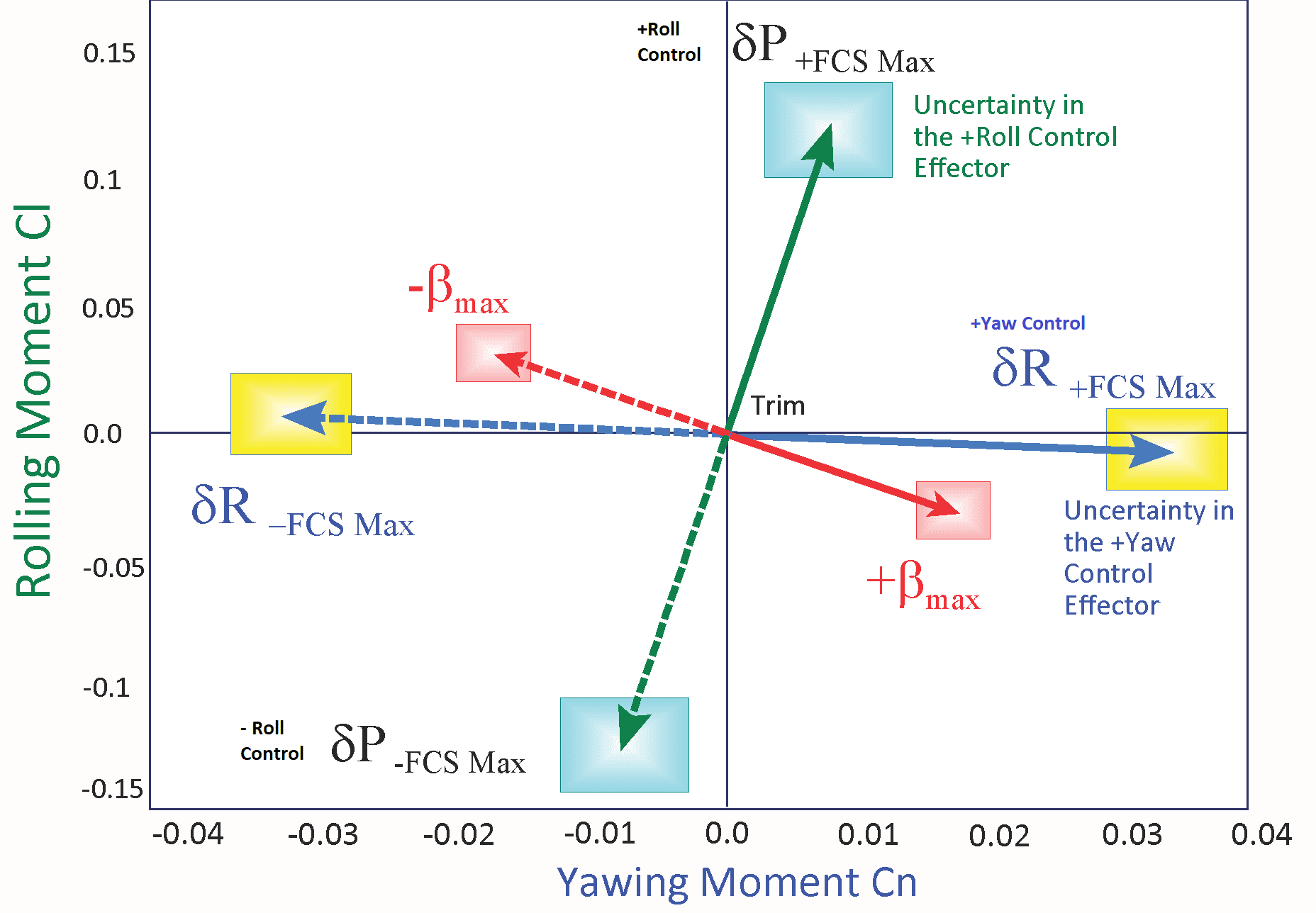
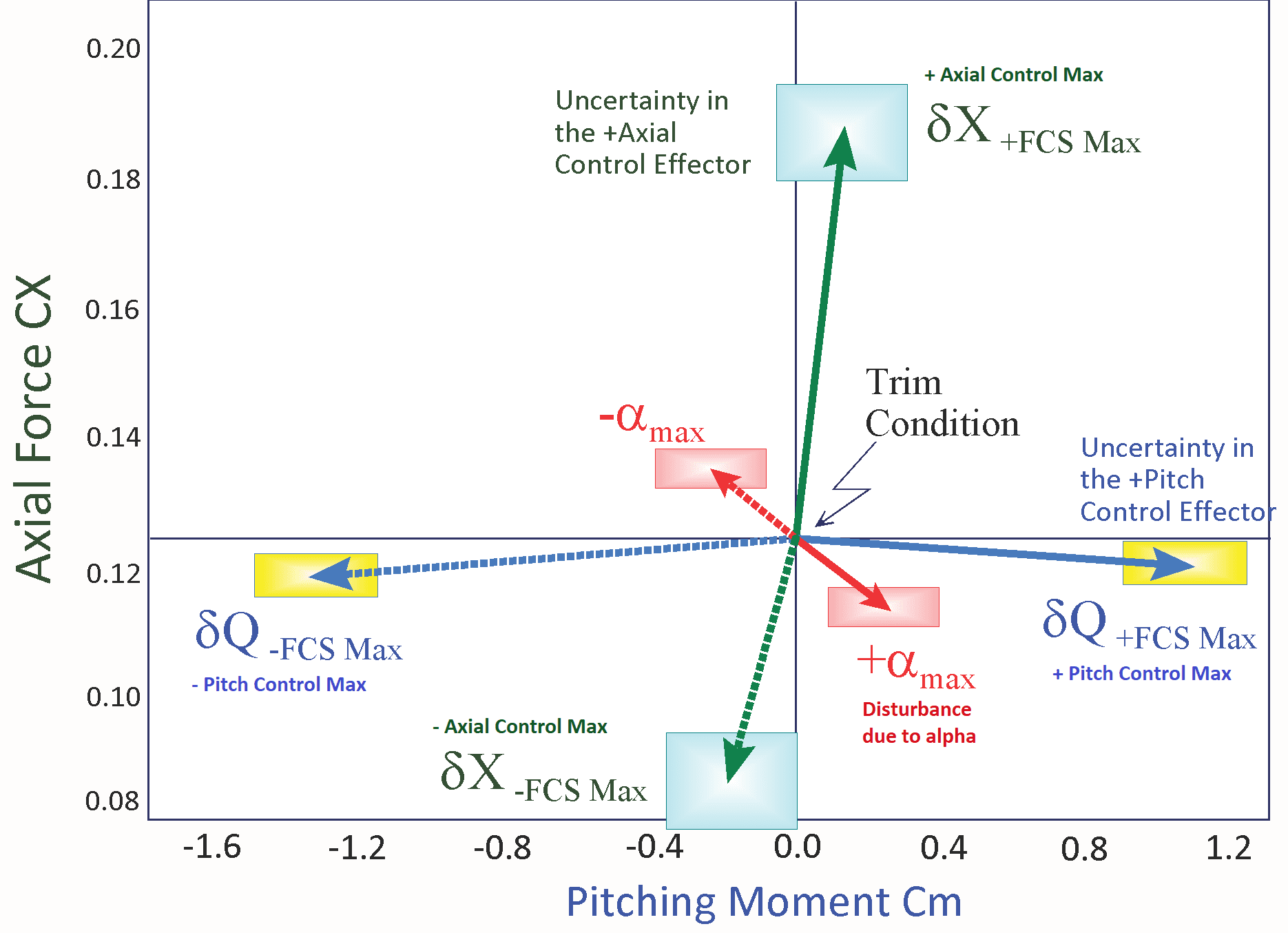
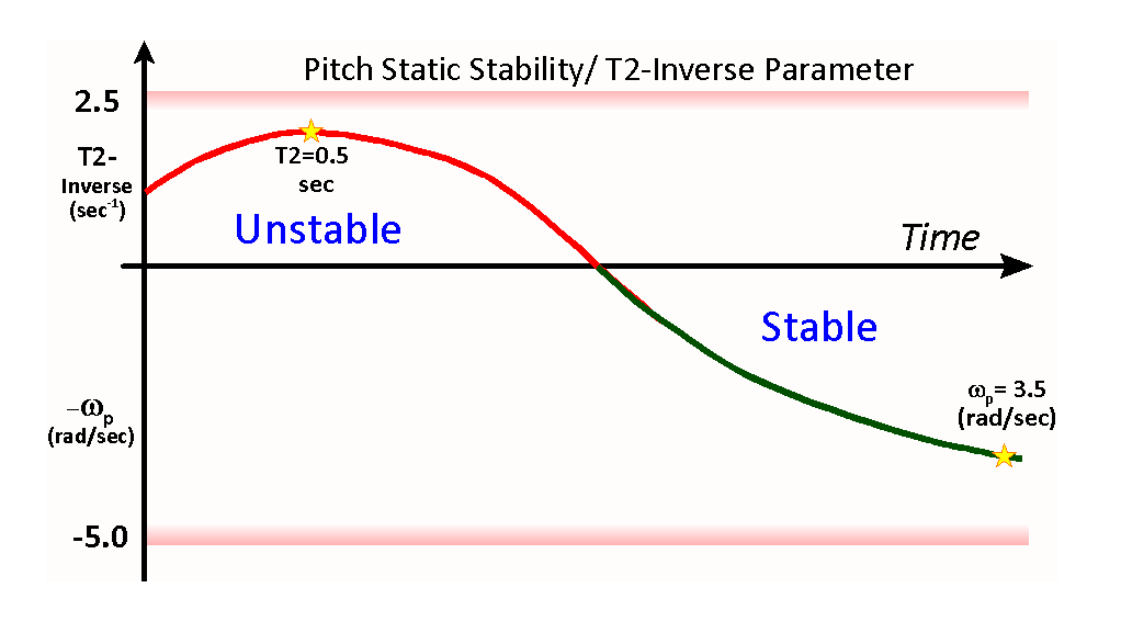
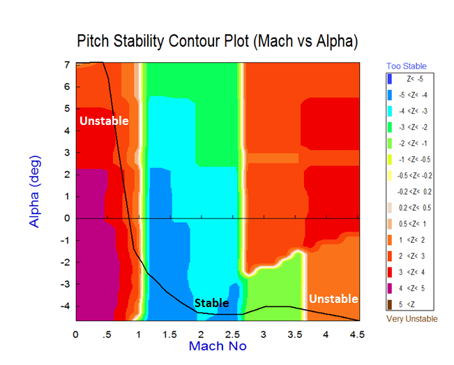
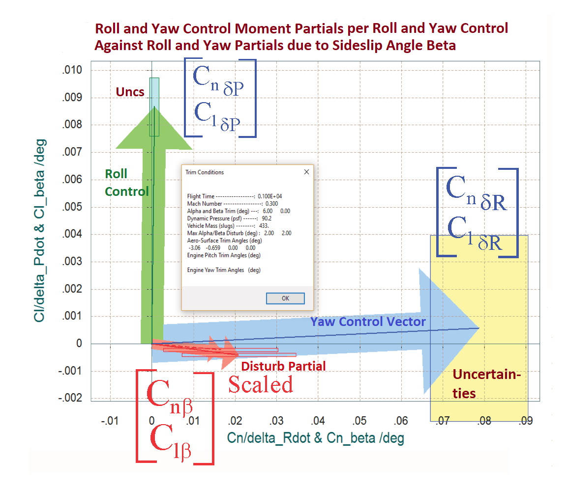
Additional tools are included in the Trim program for analyzing static performance and controllability of the effector assembly. Contour Plots display some of the important performance parameters, such as, pitch and lateral stability, the LCDP and control authority, as a function of Mach number versus alpha. They display the value of a performance parameter, color coded, in the entire Mach versus alpha range which allows the analyst to locate and avoid undesirable flight conditions. This guides the analyst in how to modify and reshape the trajectory in order to avoid undesirable flight conditions and to improve performance. Vector diagrams are two-dimensional vector plots that compare the vehicle controllability against the effects of aerodynamic disturbances at a fixed flight condition point along the trajectory. They examine the vehicle response in two directions by comparing the control moments, forces, and accelerations generated by the effector system, for example, in roll and yaw, or in pitch and normal acceleration, against the moments, forces, or accelerations generated by a wind shear disturbance (due to alpha or beta) along the same two control directions. They examine if the vehicle has enough control authority or maneuverability by analyzing the partials, to counteract the effects of disturbances along the 2 control directions.
Trimming of an aircraft is a static analysis process of balancing the moments and forces on a flight vehicle which are generated by aerodynamics and propulsion with moments and forces generated by the control effectors, such as the engines, the RCS jets, and the aerosurfaces. It requires solving the equations of motion in order to balance the forces and moments in the steady state. When a vehicle has multiple types of effectors, trimming is used to calculate the effector trim angles or throttle levels that will allow the vehicle to fly along a given trajectory, and thus size the effectors capability. In most cases we trim along a trajectory by balancing the three moments (roll, pitch and yaw). In some cases, if we have the effector availability, we may include translational degrees-of-freedom to trim, such as axial, normal, and lateral accelerations.
This tutorial derives a set of parameters that can be used to analyze and evaluate stability and performance characteristics of flight vehicles in the static sense, prior to the long process of dynamic modeling, designing the flight control system, simulations, and closed-loop stability analysis. The performance parameters are calculated directly from the vehicle data and they are used for preliminary screening of flight vehicle concepts. It allows the designer to evaluate if the airframe satisfies certain performance characteristics along the mission trajectory. This static performance analysis methodology is implemented in the Flixan program and it is demonstrated using several flight vehicle examples.
This video describes how to calculate and display some of the important performance parameters that characterize the vehicle static stability, controllability and performance characteristics along the trajectory. The performance parameters are functions of aerodynamic coefficients, trajectory variables, engine data, thrusts, trim angles etc. and they are strongly dependent on two variables, the Mach number and the angle of attack. Contour plots display the variation of a performance parameter (such as the time-to-double or controllability) along the trajectory in surface plot, as a function of Mach versus Alpha. The value of the performance parameter is color-coded on the contour surface. The vehicle trajectory appears as a line across the contour plot showing the performance at every point. It helps us evaluate the vehicle performance along the trajectory and how to modify the trajectory in order to improve vehicle performance.
This video tutorial describes the vector diagrams and their applications in analyzing flight vehicle static controllability at fixed flight conditions. Flight vehicles are usually controlled by effectors in 3 rotational directions: roll, pitch, and yaw. Controllability in the static sense is as the ability of the vehicle to respond against the environmental disturbances and to maintain a steady attitude. It is the ability of the effectors system to produce enough control torque to counteract against the torque produced by the external disturbances. Maneuverability is the ability to change directions, or the ability of the effector system to produce sufficient acceleration, and fast, in order to prevent the vehicle from diverging as a result of a wind disturbance or due to a dispersion in the angle of attack. They are analyzed using vector diagrams that compare the magnitude and direction of the combined effectors against the anticipated gust disturbances.
Utility Programs and File Management Tools
The Flixan program includes additional utilities that perform other type of functions that further refine, modify, augment and reformat the flight vehicle models. There is a utility for combining systems and matrices together using an algorithm that is not vulnerable to algebraic looping. The Flixan program, in addition to control and dynamics it includes a number of utilities which are managing input and output data files and perform other types of functions that further augment and facilitate the dynamic modeling and control analysis. There is a utility for combining systems and matrices together using an algorithm that is not vulnerable to algebraic looping, such as the algebraic loop errors often produced in Matlab when closing an algebraic loop around a system. There are also utilities for combining transfer-functions into state-systems, transforming continuous systems to discrete using (z) or Tustin transformations with variable delays, utilities for transforming systems and matrices from a system files (.Qdr) to formats that can be loaded into Matlab or converting Matlab generated data to system files. There are also utilities that modify or reduce already existing systems. Changing the system inputs and outputs, or reducing the number of variables in a system by selecting a smaller number of inputs, states, and outputs, modifying the system units by rescaling some of the variables, or creating additional outputs from the system states, state derivatives, or output derivatives. They are used for separating coupled systems to longitudinal and lateral subsystems. There are also utilities for processing the input data files in batch mode. A batch dataset contains instructions which call other programs/ utilities to process the entire input file and generate systems without interacting with the user.
Each Flixan utility reads and processes a dataset of instructions from an input file (.Inp) in a similar way as the vehicle, actuator and other Flixan programs. An input data file typically contains multiple datasets to be processed by different Flixan programs and utilities. Each dataset is processed by the corresponding utility program which typically creates a new system in the systems file according to the instructions in the dataset. The input data-sets are created either manually by copying and modifying the dataset from another file using a text editor, or more efficiently, each utility program provides the capability of generating its own type of dataset interactively, by means of menus and dialogs, as shown in the examples. The Input File Manager Utility is used to edit an input file, browse the comments, delete or relocate datasets, copy datasets from one input file to another, and process each individual dataset either interactively or in batch mode. The systems files contain individual matrices such as gains or mixing logic, state-space quadruple systems (A, B, C, D), or Linear Fractional state-space systems which contain 9 matrices and are used for control design and robustness analysis. The Systems File Manager Utility is used to edit, browse, delete or relocate systems or matrices, and copy items from one systems file to another. The Batch Processing Utility is used to process Flixan datasets in batch mode. A batch is a dataset in an input file (.Inp) that includes a set of commands that call other Flixan programs to perform certain functions and to process other datasets in batch mode. This is faster because it executes without user interaction. A batch set is processed using the File Manager utility.
This Flixan utility is used for managing input data files. The Flixan input files contain multiple datasets to be processed by Flixan utilities. The Input File Manager Utility is used to edit, browse the comment notes of datasets, process each individual dataset either interactively or in batch mode, delete or relocate datasets, and copy datasets from one input file to another.
The Flixan Batch Processing Utility is used to process batch type of datasets. A batch is a dataset in an input file (.Inp) that includes a set of commands that call other Flixan programs to perform certain functions and to process other datasets in batch mode, which is faster because it executes without user interaction. A batch set is processed by the File Manager utility.
This Flixan utility is for managing system files. The Flixan system files contain individual matrices such as gains or mixing logic, state-space systems (A, B, C, D), or Linear Fractional state-space systems containing 9 matrices and used for H-infinity control design. The Systems File Manager Utility is used to edit, browse, delete or relocate systems or matrices and to copy items from one systems file to another.
Flight Vehicle Modeling and Control Design Tools
Flight Vehicle Dynamic Modeling
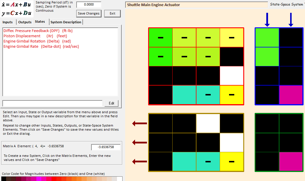
This section describes the operation of the flight vehicle modeling program and the flexible spacecraft modeling program that generate vehicle state-space systems for simulations and control analysis. It also describes the actuator modeling program which implements several types of actuator models.
Control Analysis and Design
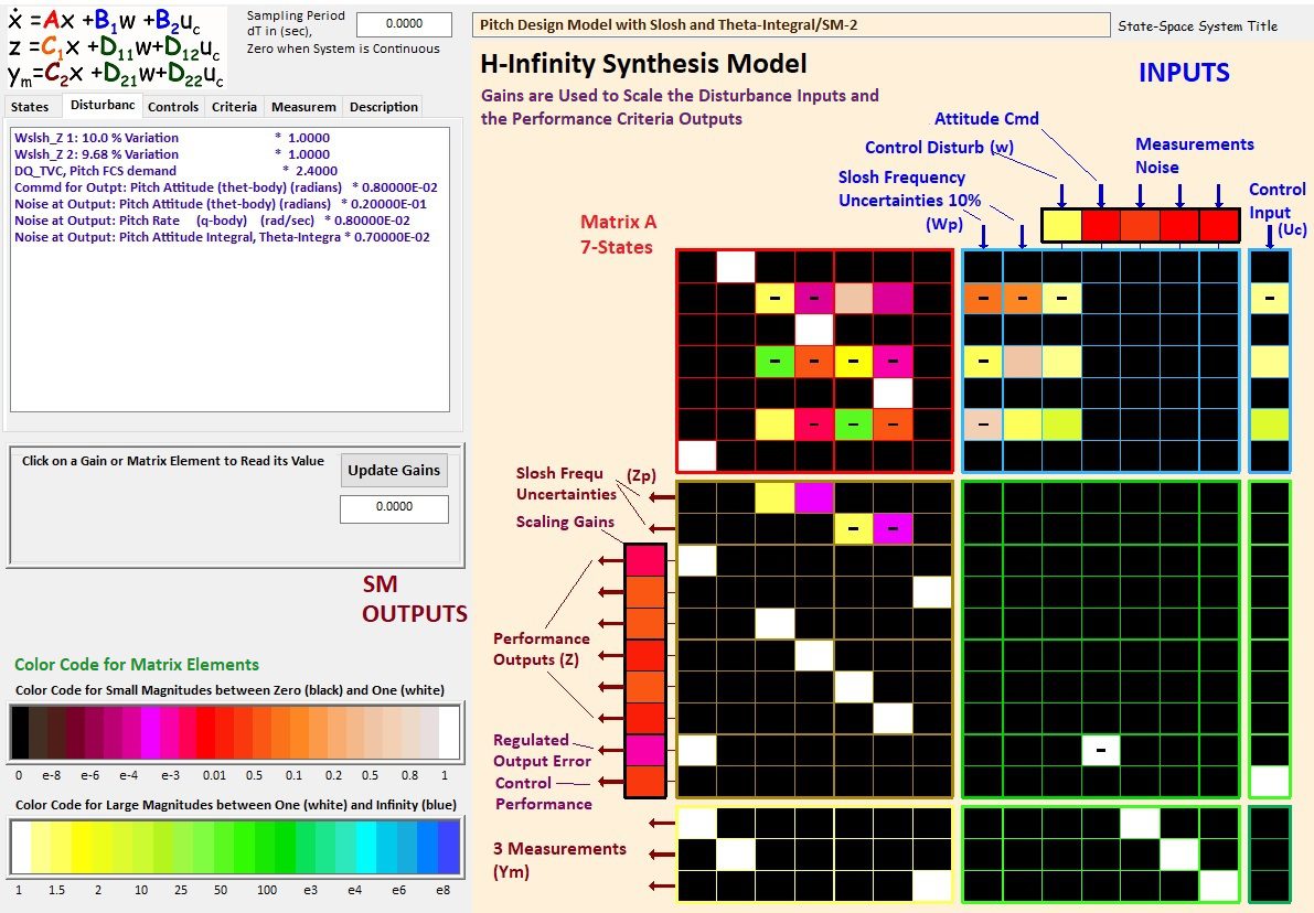
This section describes methods and tools for control system design and for analyzing stability and robustness. The LQR/LQG and H-Infinity methods are commonly used for control system design. Additional methods are included for analyzing the control system’s robustness to parameter uncertainties, and includes classical frequency response analysis tools.
