Examples of Rockets and Launch Vehicle Designs
In this section we present modeling examples of booster type of Launch Vehicles which are mainly controlled by thrust vectoring engines and RCS jets, although in some cases aerosurfaces are also used. The examples include the Space Shuttle during first and second stages, performing stability and vibration analysis due to structural coupling between vehicle and payload, flexibility analysis and control design of classical launch vehicles, rocket-planes, multi-engine launch vehicles controlled by differential throttling, air-launched rockets, trimming of the effectors along the trajectory, static performance analysis, and non-linear 6DoF simulations. The dynamic models include propellant sloshing, flex modes derived from finite-element models, actuator modeling, and tail-wag-dog effects produced due to dynamic coupling between the flex vehicle and actuators. The 6DoF simulations are implemented in Simulink using models and control parameters derived from Flixan.
Space Shuttle Ascent at Maximum Dynamic Pressure
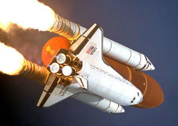
In this example we are modeling the Space Shuttle vehicle during first stage and analyzing the flight control system stability and performance at maximum dynamic pressure. During first stage the Shuttle propulsion system consists of three Shuttle main engines, (SSME) and two solid rocket boosters, (SRB). The vehicle attitude and direction are controlled by gimbaling the engines in pitch and yaw. The attitude, rate, and acceleration are measured by an IMU, rate gyros, and accelerometer sensors which are located at the top section of the SRBs. Roll attitude and rate are measured by sensors located in the orbiter vehicle. Inside the orange external tank (ET) there are two large tanks containing the liquid oxygen (LOX) in the front section and a liquid hydrogen (LH2) in the aft section of the ET. During Max-Q the tanks are partially filled and fuel sloshing is a potential problem of destabilizing the vehicle and generating oscillatory disturbances. The aero surfaces are not used during ascent but they are scheduled open-loop to minimize actuator loading. Structural flexibility due to engine gimbaling is significant and it is included in the analysis.
Shuttle Payload with Coulomb Damper Vibration Analysis
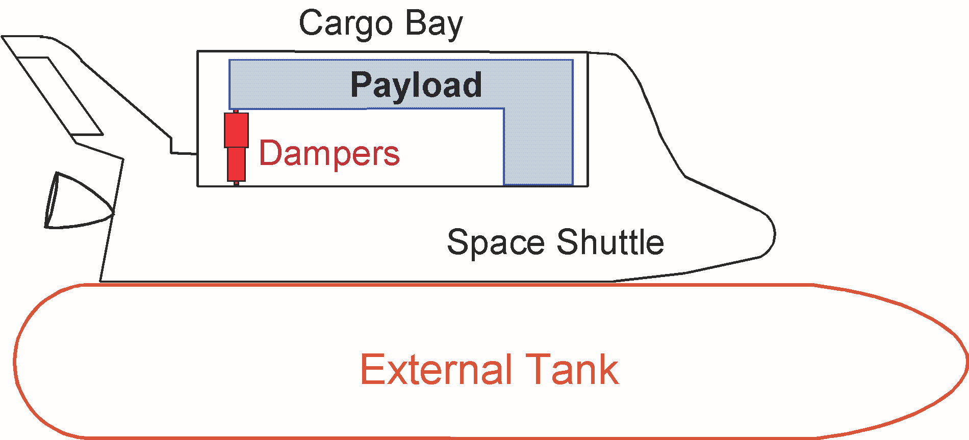
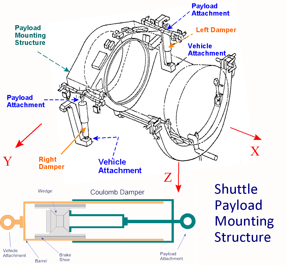
Control engineers are often challenged with vibration problems that can occur due to dynamics and control system interactions. They often require smart control design solutions that include flexibility compensation filters. In some cases, however, the only practical and robust solution to structural vibrations is a mechanical fix. The following example presents such a design challenge that requires non-linear control analysis and the use of the Describing Function (DF) method because it involves non-linearities that produce structural oscillations. The flex mode instability problem was predicted using linear analysis on the Shuttle ascent 2nd stage in a mission when carrying a heavy and flexible payload. A software fix using a notch filter was not practical because the mode was very strong and at low frequency. Filtering would deteriorate the rigid-body phase margin and degrade robustness. A hardware solution was implemented instead by mounting a pair of non-linear coulomb dampers to attenuate the structural vibration to acceptably small oscillation amplitudes. The coulomb dampers are non-linear energy dissipating devices connected between the payload and the cargo bay.
Air Launched Twin Booster Design and Simulation
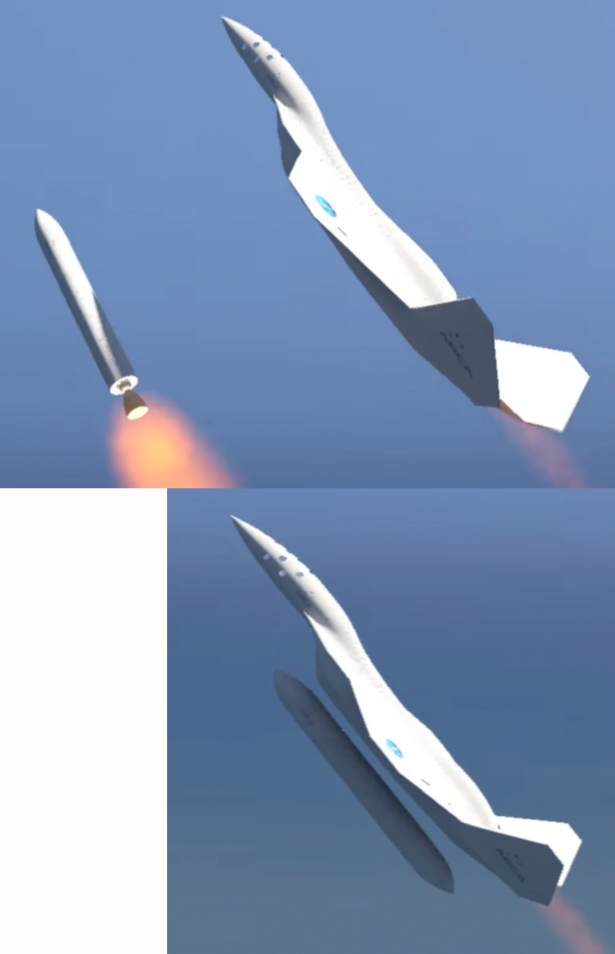
The purpose of this example is to familiarize the student with the entire process of designing, analyzing, and simulating the flight control system for a special type of launch vehicle that is released from an aircraft, which makes the take-off more dynamic and with some adverse transients. The advantages of an air launched vehicle are: reduced weight and cost because the first stage is a reusable aircraft, the engine size and thrust are reduced, plus the structural loading on the launch vehicle due to aerodynamics is reduced because the air density and dynamic pressure are lower at high altitudes. The carrier aircraft is also special because it is capable of climbing up to high altitudes and to release the booster in an upward direction, that is, with a positive flight-path angle g. This maneuver requires an aircraft with a rocket that helps the aircraft to climb at high altitude and to release the vehicle just before stalling, in an upward direction and at low speed. Then the aircraft rolls to the side to avoid impact, and the launch vehicle engines ignite 5 seconds after separation for safety in case of an explosion. The release at high altitude in an upward gamma direction and at low dynamic pressure, are the important ingredients for optimizing the trajectory that maximize the payload weight to orbit capability
Apollo/ Saturn 5 Launch Vehicle Design with Flexibility Analysis
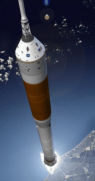
This is a launch vehicle similar to an Apollo/Saturn type cylindrical booster consisting of two stages. We will analyze it during first stage and at maximum dynamic pressure. It is powered by a single 3 million pounds thrust solid rocket motor (SRM) that gimbals in pitch and yaw and provides acceleration in the x axis. Due to cylindrical symmetry the pitch and yaw axes are identical and we will analyze stability only in the pitch and roll axes. The roll axis is controlled by 8 RCS thrusters located around the peripheral of the cylinder at 90 degrees apart and firing in the ±z and ±y directions. This vehicle is long and very flexible and the purpose of this study is to analyze the effects of structural flexibility on the control system stability by defining a satisfactory stiffness of the conical inter-stage structure that joins the first and second stages together. We will, therefore, analyze and compare the flex stability using three separate finite element structural models using nominal stiffness, soft, and stiff structural models. We will also analyze and compare vehicle responses to attitude step commands and to wind-gust disturbances using sensors placed in different vehicle locations. For pitch stabilization the flight control system uses attitude and rate feedback from a gyro and angle of attack feedback from a vane sensor that is located in the front part of the vehicle. The alpha-feedback is also needed for load-relief during high Q-bar conditions. For roll control we define the RCS jet selection logic, phase-plane and the RCS dead-band
Shuttle Vehicle with a Reusable First Stage Liquid Booster
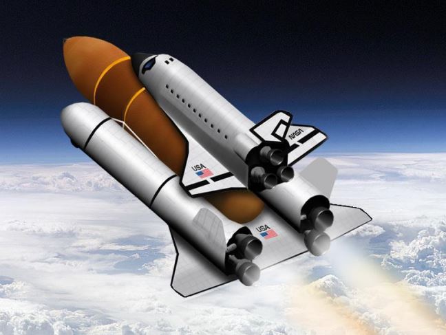
In this example we have a Space Shuttle type of vehicle during first stage which is attached to an airplane type of booster with multiple engines. After first stage separation, the booster has enough propellant to return to the launch site and it lands like an airplane. The Shuttle vehicle is attached to an external tank and the tank is attached to the first stage booster aircraft. This example is intended to demonstrate the design of a TVC engine steering logic that combines thrust vectoring (TVC) and differential throttling together to control the vehicle. Differential-throttling is more effective in yaw because of the long y-moment arm. It also demonstrates how we can take advantage of the multiple engines to design a mixing-logic algorithm that can be reconfigured in the event of an engine failure without changing the flight control law. We will analyze only one flight condition, at max dynamic pressure, because it is the most critical for stability and structural loading. The approach can be applied to other flight conditions
Trim and Static Analysis of a Single Stage to Space Rocket Plane
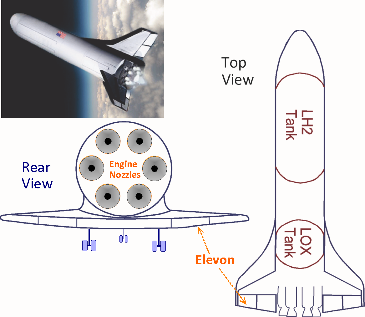
In this example we will design a single stage rocket with wings that takes off vertically like a launch vehicle, it goes into orbit and it re-enters the atmosphere to land on a runway like a Space Shuttle. It operates in three phases: ascent, on-orbit, and re-entry. In this analysis, however, we will only study the ascent phase, create models, design a flight control system for different flight conditions along the ascent trajectory and analyze its performance in the critical flight conditions to make sure that flight vehicle controllability, performance and stability are acceptable throughout ascent. During ascent the vehicle is controlled by 6 gimbaling engines which are identical and they gimbal in pitch and yaw. Since the vehicle mass properties change with weight, a thrust vector control (TVC) logic is calculated at each flight condition to convert the roll, pitch, and yaw flight control commands to gimbal deflections for each engine and the TVC gains vary with time. The engines burn liquid oxygen (LOX) and liquid hydrogen (LH2) and the vehicle carries two big tanks for the two propellants which are sloshing and they produce a significant amount of disturbance excitations on the vehicle that must be analyzed for stability. Structural flexibility and tail-wag-dog dynamics are also included in the models. The vehicle also has aerosurfaces which are only used during descent
Reusable Launch Vehicle Space Plane Design
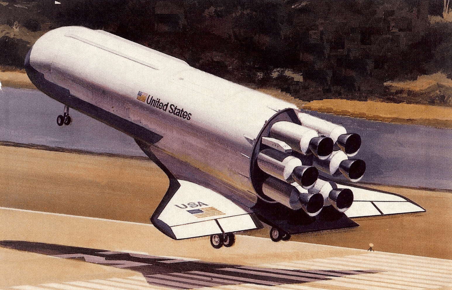
In this example we will analyze a launch vehicle with wings. It takes off vertically like a launch vehicle, goes up into earth orbits and returns to land like a glider without engine power. During ascent it uses 6 engines that provide a total thrust of 350,000 (lb). The engines are of different types and thrusts to demonstrate the Flixan effector combination feature. The first two engines are gimbaling ±14° in pitch and ±12° yaw and they have constant thrusts of 70,000 (lb). Engines #3 and #4 are also gimbaling but only ±5° in pitch and yaw and they can also vary their thrusts between: 9,200 to 100,000 (lb). Engines #5 and #6 are also varying their thrusts from 9,200 to 100,000 (lb), but they are fixed and do not gimbal. The launch vehicle also uses two elevons which are located at the wings. They are used to control roll because the TVC engines are too close together and they cannot provide sufficient roll controllability. This vehicle does not have a vertical tail and rudder. During descent the engines are not active and the vehicle uses the two elevons for pitch and roll control and two lateral RCS jets for yaw control which are located at the front. This example demonstrates the effectors combination mixing logic algorithm for combining different types of effectors together and optimizing the control authority of the vehicle
Air Launched Booster Rocket Design
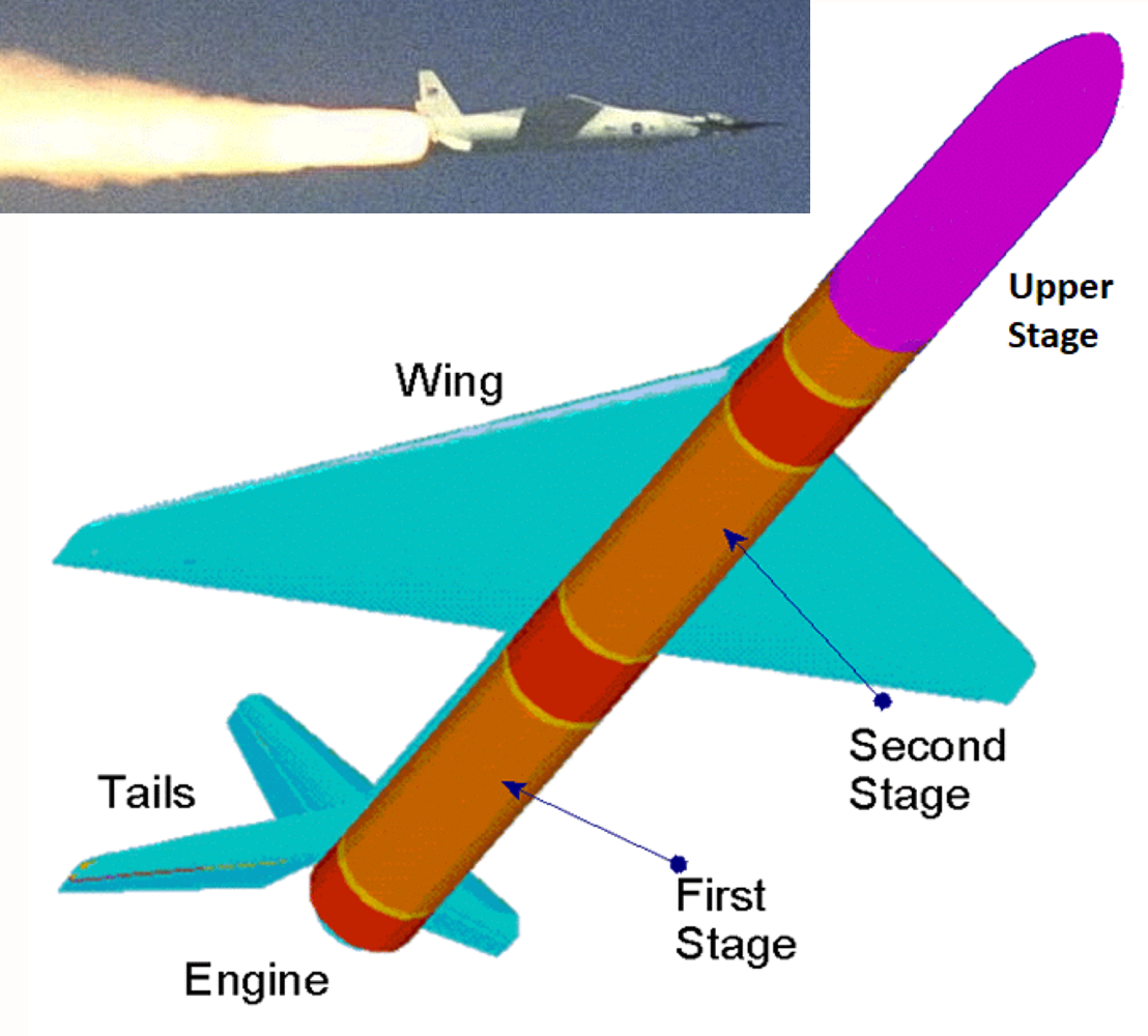
In this example we have a booster rocket that is launched after being dropped from a carrier aircraft. It is released from an altitude of 20,000 (feet) and it glides like an airplane for a while by means of a system of wings and tails that help it separate from the aircraft, prevent it from losing altitude, and pointing it upwards before igniting a 400,000 (lb) booster engine. The wings and tails remain attached for 20 seconds providing lift and helping to achieve the required flight path angle. After the wings separate the vehicle continues to ascent to orbit like a typical booster rocket. At T=500 seconds the first stage separates and the second stage ignites. During the unpowered glide-phase the vehicle is controlled by two elevons and a rudder located in the tail section. During the boost phase the vehicle is controlled by the TVC engine in pitch and yaw and also by the aero-surfaces. After the wings and tails separate a pair of RCS jets is used to control roll. In this example we will analyze the unpowered glide phase, the boost phase with the wings and tails attached, and the boost phase without the wings and tails.
Classical Launch Vehicle Design and 6DoF Simulation
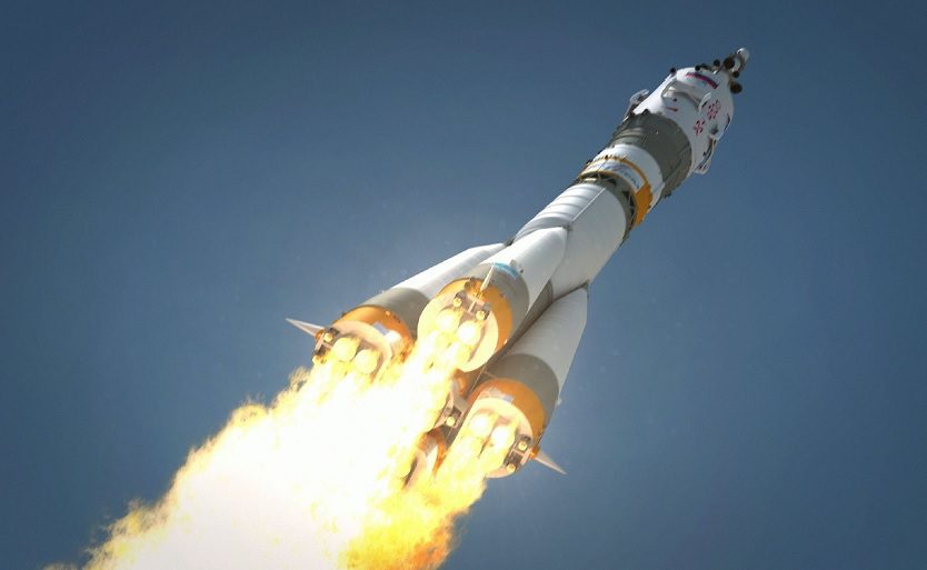
In this example we will analyze a two-stages launch vehicle from lift-off to orbit insertion. We begin in Section-1 with a static analysis which is based on mass properties, trajectory and aero data to analyze the static stability and performance qualities of the vehicle, prior to control design. In Section-2 we will design the first-stage control system and analyze the system stability at different flight conditions, including: lift-off, max-Q, and pre-separation. The Flixan program will be used to create the vehicle models including propellant sloshing and structural flexibility. In Section-3 we will design the control system during second stage and perform similar analysis including slosh and flexibility. In Section-4 we will analyze the system robustness to parameter uncertainties using m-analysis. In Section-5 we introduce non-linear propellant sloshing models to analyze the effects of instabilities that were observed when using linear slosh models. In Section-6 we have included a 6DoF simulation model of the vehicle, from lift-off to orbit insertion, including detailed descriptions of the vehicle subsystems and the control system.
